Open the last bracket drawing your team sent out and look at the tolerance block. I would bet it says ±0.1 mm on every dimension, because that is what the CAD template puts there, and for years every stamping drawing I signed off on the buying side carried that same block, with the engineering team’s review behind it. What I only learned once I was on the manufacturing side with VIA INDIGOS is that sheet metal tolerances are not 1 number for the part, they are 1 number for each kind of feature, and the kind is decided by how the die makes it. A hole pierced in 1 station holds ±0.05 mm without trying, a shape formed in the die holds about ±0.1 mm, and any dimension that crosses a bend holds ±0.15 to 0.2 mm. So let me take 1 plain bracket and go through it feature by feature, so you can see what to write on each line and pay for nothing the part does not need.
Let’s start with how each feature is made, not with the number you want
The drawing in front of you is an L bracket, 2 mm cold rolled steel, 2 holes in the base, 1 emboss between them and a flange bent up at the end, and the CAD system has put ±0.1 mm on every dimension because that is the default. Send that drawing out and 1 of 3 things happens: the plant quotes it with a question, the plant quotes it and quietly ignores the number, or the plant quotes it with a secondary operation you did not know you were paying for. The way out is simple, so look at each dimension and ask what makes it, a punch, a form station or a bend, because that answer sets the tolerance before anyone picks a number.
I have coloured the bracket by that answer, and the rest of this note walks the 3 colours in order, starting with the blue ones, because they are the easiest to get right and the easiest to waste money on.
Holes and edges the die cuts in 1 hit
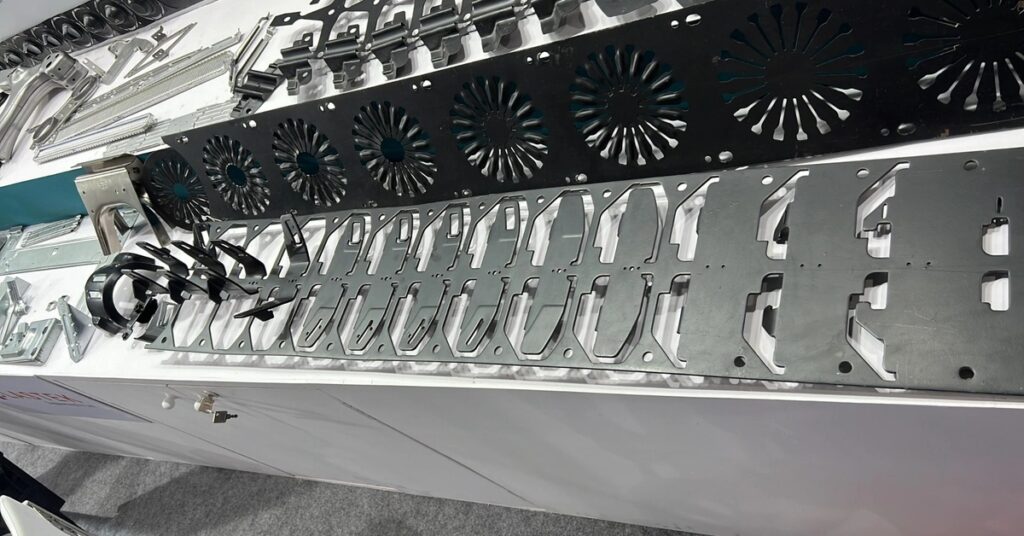
A pierced hole is a hole a hardened punch pushes straight through the sheet, so the hole is the size of the punch, and a blanked edge is cut by the die the same way, so the edge is the size of the die. That means the dimension on your part is really a dimension on a piece of tool steel that was ground to a few microns, which is why a hole diameter and a hole to hole distance pierced in the same station hold ±0.05 mm all day on a progressive die, and will keep holding it until the punch wears, which on 2 mm mild steel is hundreds of thousands of hits.
The 40 mm between the 2 holes on the bracket is this kind of dimension, and ±0.05 is a fair thing to write, as long as both holes come from 1 station.
The moment the 2 features come from different stations the strip has moved between them, and the pitch of the strip feed, the pilot pins that locate it and the clearance in the die all enter the number. Hole to edge across 2 stations holds about ±0.1 to 0.15 mm, so write ±0.15 unless you have asked the tool room to put both features in 1 station, which it will often do if you ask before the die is designed and almost never after.
The tool room decides this at the strip layout stage, which is the drawing of how your part sits on the coil as it moves through the die, so send your drawing with the critical dimensions marked, not just the numbers. The charcoal dimension on the plate is a different animal, because nothing cuts it.
Embosses, louvers and the other shapes the die forms
An emboss is a raised shape pushed into the sheet, a louver is a slot with one side pushed up, and an extruded hole is a hole with a short collar pulled out of the sheet, and all 3 are formed, which means the steel was pushed into a shape rather than cut to one. Steel pushed into a shape comes back a little when the punch lifts, so the height of the 2 mm emboss on the bracket depends on the punch depth, the sheet thickness that day and how that coil of steel yields, and a formed height holds about ±0.1 mm in a well made die.
The first article report will usually show that height drifting a few hundredths through the first thousand hits as the die settles, which is normal and nothing to argue about. Write ±0.1 on a formed height and the plant will nod, write ±0.05 and the plant adds a coining hit, which is a station that squeezes the shape to final size under heavy load, and that costs on the die and per piece, and is only worth it if a mating part actually needs it. The orange dimensions are where most of the arguments happen, so let me spend more time there.
Any dimension that crosses a bend
The 35 mm flange on the bracket is measured from the outside of the base to the top of the upright, and it crosses the bend, so 2 things nobody at the plant controls now sit inside it. The first is sheet thickness, because 2 mm cold rolled steel arrives from the mill within roughly a tenth of a millimetre either way, and a thicker coil moves the bend line and the flange length with it. The second is springback, which is the steel opening up by a degree or so after the punch lifts, and the die compensates for the average coil, not for every coil.
Put those together and a flange length holds ±0.15 to 0.2 mm in a die, and the same goes for a hole to bend dimension, because the hole was pierced flat and the bend moved afterwards.
Write ±0.2 on the flange and ±0.5 degrees on the angle and the die will hold both without a second thought. If the flange truly needs ±0.1 because the bracket mates with a machined face, say so on the drawing and expect the plant to pierce the holes after forming or to add a restrike, which is a second light hit on the bend to set it, and that is the right answer for a few parts and the wrong default for all of them. There is 1 more number buyers ask about more than any other, and the plant does not set it at all.
The thickness itself belongs to the mill
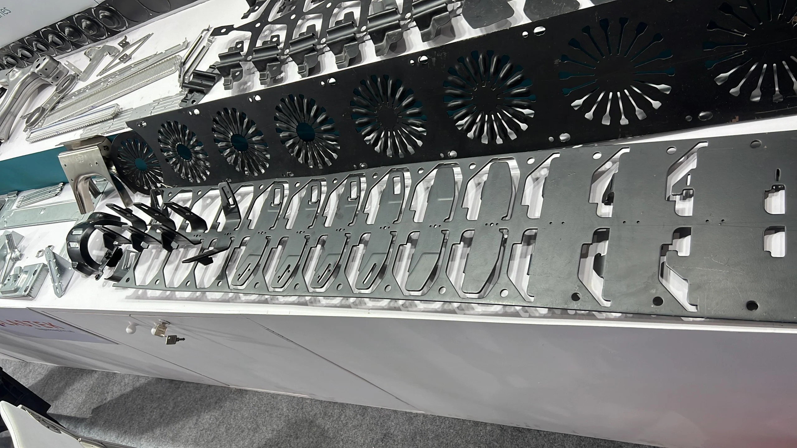
The sheet metal thickness tolerance is the one buyers ask about most, and it is the one the plant does not set. Cold rolled sheet is bought to a standard, ASTM A1008 in the US or the equivalent IS or EN grade in India, and that standard carries the thickness band for each nominal gauge and coil width, which is why the mill certificate governs and the drawing should name the standard and the nominal rather than invent a tolerance. On a 2 mm sheet the band is roughly ±0.1 mm depending on coil width, and every bend in the part inherits it.
If the part needs a tighter band, half standard tolerance can be bought from the mill at a price, but on a bracket it is rarely worth it, because a tenth of a millimetre on thickness changes the weight more than the function. Where it does matter is on the flange length and the bend, which is why the orange numbers are what they are, and why a drawing that holds the thickness at ±0.05 is asking the plant to buy special coil for a dimension it cannot see. Everything so far has assumed a die, and below a few thousand pieces a year there is no die, so the numbers change.
Laser, turret and press brake, when there is no die
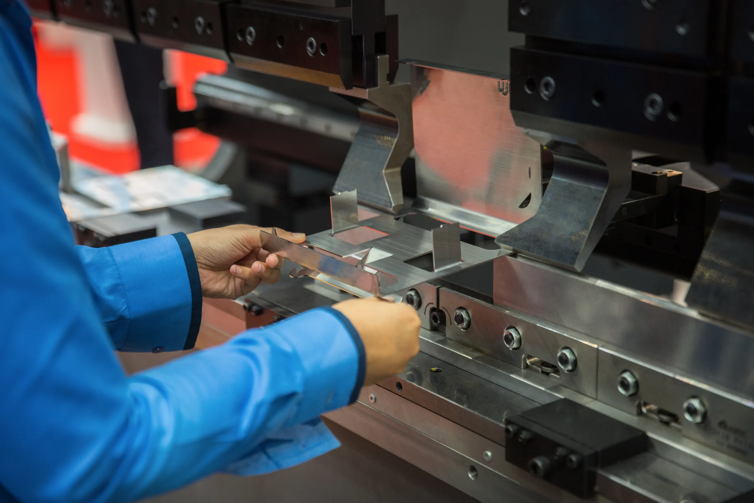
Below a few thousand pieces a year the bracket is not stamped, it is cut on a fiber laser or a turret punch and bent on a CNC press brake, and the numbers move. A laser profile and a laser cut hole hold about ±0.1 mm, a turret punched hole holds ±0.1 as well, and the flange off a press brake holds ±0.25 to 0.5 mm depending on its length, because the back stop and the operator set every bend rather than a die setting it once. Bend angle on a brake with the springback compensated holds ±0.5 degrees, and a long thin flange holds less.
The plant will quote ±0.1 on the flat and ±0.3 across the bend as its fabrication standard, and a drawing that asks for the die numbers on a brake part is asking for a fixture and a check that nobody priced. So the same bracket carries 2 tolerance sheets depending on volume, and the honest thing is to write the one for the route you are actually buying. Two lines are missing from most drawings either way, and they cause more rejections than any dimension.
Flatness, burr and the lines nobody writes
A blanked part is not flat, because it carries the curl the die put in it, so flatness on a plain blank runs around 0.2 to 0.5 mm over 100 mm, better after a flattening station, and the drawing should carry a flatness value only on the face that touches something. Burr is the thin sharp lip the punch leaves on the exit side of every cut, and it runs up to about a tenth of the sheet thickness on a sharp die, so on 2 mm steel write burr max 0.2 mm and mark the burr side if a hand will touch the part, because a plant that is not told puts the burr wherever the die was easiest to build.
Neither line costs anything if it is on the drawing before the die is designed, and both cost a deburring operation or a rejected lot if they turn up afterwards. Put them next to the material note, where the inspector will look for them, and then the whole walk through collapses into 1 sheet, which is where I want to take you next.
The tolerance sheet for a stamped bracket
The sheet below collects everything above. The middle column is what a good die holds on a 2 mm steel part, labelled typical because a thinner or softer material holds tighter and a 6 mm plate holds wider, and the drawing governs. Where nothing is written, the plant works to the standard sheet metal tolerances in ISO 2768 class m, which on 30 to 120 mm is ±0.3 mm, so a critical dimension inside that band has to be called out on its own.
| Feature on the part | Made bywhich station or machine | Die holdstypical, 2 mm steel | What to write |
|---|---|---|---|
| Hole diameter | Pierce punch | ±0.05 mm | ±0.05, or the fit if a pin goes in |
| Hole to hole, 1 station | Pierce, same hit | ±0.05 mm | ±0.05, mark as critical |
| Hole to edge, 2 stations | Pierce, then blank | ±0.1 to 0.15 mm | ±0.15 |
| Blanked outline | Blanking die | ±0.05 to 0.1 mm | ±0.1 |
| Emboss or louver height | Form station | ±0.1 mm | ±0.1 |
| Flange length across a bend | Bend station | ±0.15 to 0.2 mm | ±0.2 |
| Hole to bend | Pierce flat, then bend | ±0.15 to 0.2 mm | ±0.2 |
| Bend angle | Bend station or brake | ±0.5 degree | ±0.5 degree, ±1 on thick plate |
| Laser profile or hole | Fiber laser | ±0.1 mm | ±0.1 |
| Press brake flange | CNC brake, back stop | ±0.25 to 0.5 mm | ±0.3 short, ±0.5 long |
| Sheet thickness | The mill | About ±0.1 mm on 2 mm CRS | Nominal and the material standard |
| Flatness | Blank, flattening station | 0.2 to 0.5 mm per 100 mm | Only on the face that mates |
is free on the first 2 lines, because the punch holds it anyway. Write the rest as shown and the die costs you nothing extra, and the plant quotes without a single question. I learned that from 2 drawings of my own, which is how I want to close.
The 2 drawings that taught me this
The first was a bracket drawing with ±0.1 mm on every line, which is how the CAD template came and how I sent it out for years from the buying side, with the engineering review done and the part in production without a problem. The quote carried a line called sizing operation, and I approved it, on that part and on the ones after it, for about 2 years before I understood what it was. It was a restrike station in the die and a few cents on every piece, paid for a flange nobody ever measured to ±0.1, and no one at the plant was going to tell a buyer that his drawing was asking for something the part did not need, because the plant was being paid for it.
The second drawing went wrong the other way. It had a hole to bend dimension that mated with a machined boss, and it sat at the general tolerance because it looked like any other dimension on the page. The first production lot rocked on the boss, and when we measured it the parts were all inside ±0.3, which is exactly what ISO 2768 m allows on that length, so the die was fine and the drawing was wrong.
On the automotive brackets we run now, the DFM note that goes back inside 48 hours marks each dimension as die cut, formed or across a bend, so the buyer sees which numbers are free and which ones cost a station before the die is designed. Send your drawing before the die is quoted, and ask whoever quotes it to mark every dimension the same way.
Questions engineers ask about sheet metal tolerances
What is a standard sheet metal tolerance?
If the drawing says nothing, most plants work to ISO 2768 m, which is ±0.1 mm up to 6 mm, ±0.2 mm from 6 to 30 mm and ±0.3 mm from 30 to 120 mm. Any dimension that needs better than that has to be written on the drawing on its own.
What tolerance can sheet metal bending hold?
A flange length across a bend holds ±0.15 to 0.2 mm in a progressive die and ±0.25 to 0.5 mm on a CNC press brake, with the bend angle at ±0.5 degrees when the springback is compensated. Thicker or springier material holds wider.
What is the thickness tolerance of sheet metal?
Thickness is set by the mill standard, ASTM A1008 for cold rolled steel in the US, and on a 2 mm sheet it is roughly ±0.1 mm depending on coil width. The mill certificate governs, and the drawing should carry the nominal and the standard, not an invented band.
How tight can a progressive die hold a hole?
Hole diameter and hole to hole in the same station hold ±0.05 mm, because both come straight from the ground punch. Hole to a feature in another station holds ±0.1 to 0.15 mm, and hole to a bend holds ±0.15 to 0.2 mm.
Does a tighter tolerance always cost more on sheet metal?
Not on a die cut feature, where ±0.05 mm is what the punch holds anyway. On a formed feature or across a bend it adds a sizing or restrike station to the die and a few cents per piece, and on a press brake part it adds a fixture and an inspection step.